PS5 UART Diagnostics Guide
Table of Contents
- Overview
- Prerequisites
- Setup Instructions & Getting Started
- UART Pinout References
- CH341A UART Module 3.3V Modification Guide
- Troubleshooting
- Questions & Answers
- Recommended Hardware
- Fuse Information and Details
- Additional Tips for UART Usage
- Want to Help or Contribute?
Overview
Welcome to Console Service Tool UART for PlayStation 5! This tool is designed to assist technicians in diagnosing hardware issues such as GDDR6 memory, APU, HDMI shorts, and more using UART communication and reading the error codes directly from the console. With the communities help with reverse engineering codes, hardware solutions and repairs related to specific errors. We can continue to update this tool and provide a great value to the repair industry.
Prerequisites
Before getting started, make sure you have the following:
- PlayStation 5 Console: Ensure you have a PlayStation 5 console.
-
UART Module: Obtain a UART module compatible with the PlayStation 5 console. (CH341A)
*Note: If using the CH341A UART module, you will need to modify it to work with 3.3V instead of 5V. Refer to the following documentation for guidance on how to perform this modification: CH341A UART Module 3.3V Modification Guide. - Console Service Tool: This software or similar software to read the error codes from UART.
Setup Instructions & Getting Started
-
Connect UART Module and Install Drivers: Connect the UART module to your computer.
Note: Ensure that any required drivers are installed following the manufacturer’s instructions. -
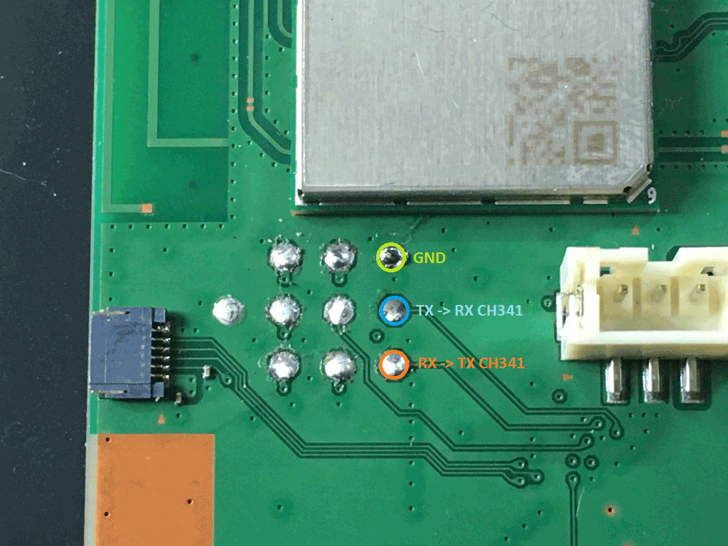
Solder UART Wires to Module & PlayStation 5: Using three wires in total: Reference Images
- Connect the first wire from the RX pin on the UART module to the TX pin on the PlayStation 5.
- Connect a second wire from the TX pin on the UART module to the RX pin on the PlayStation 5.
- Connect a third wire from the GND pin on the UART module to the GND pin on the PlayStation 5.
-
Supply 12V Power to the PlayStation 5: Connect the PlayStation 5 to a powered wall outlet or supply 12V using a DC power supply.
Note: Do not power on the PlayStation 5 at this time. -
Reading Codes from Multiple States: The PlayStation 5 has multiple states from which we will try to read error codes. We will want to read any codes that may be currently stored in memory to get an idea of previous faults and save these for reference. The following states are where we will try to isolate our error codes from:
- Standby state
- 1st boot sequence (powering-on state)
- Powered-on state
- 2nd boot sequence (powering-on state)
Note: Each time we read the codes, we will want to save a reference of the codes, if any. Then, clear all codes before moving on to the next state.
-
Previous Error Codes: Before doing anything, we will want to get a snapshot of the error codes that have been previously thrown into memory. After connecting the PlayStation 5 and supplying 12V either by power supply or a powered outlet. Select “Read All Codes” in Console Service Tool. Save the information, then in Console Service Tool select “Clear All Codes”. Disconnect 12V power from the console and allow 1 minute for the console to completely power off.
Note: Console Service Tool saves error logs in the */logs directory. -
Standby State: Supply 12V to the console again either by power supply or a powered wall outlet. Do not power on console. Wait 1 minute for the console to initialize Standby state. Select “Read All Codes” in Console Service Tool. If any errors display during this process, they are most likely related to standby state. Save the information. If error codes are displayed, it is recommended to diagnose these codes before proceeding. “Clear All Codes” in Console Service Tool but do not disconnect the 12V power supply. Leave it connected. You should be in Standby state with no error codes.
-
1st Boot Attempt: Press the Power button on the PlayStation 5 to power on the console. Note: Do not worry if the console does not fully power on. If it just beeps, shuts down, or does not respond. This may be normal. Select “Read All Codes” in Console Service Tool. If any errors display during this process, they are most likely related to powering-on state. Save the information. If error codes are displayed, it is recommended to diagnose these codes before proceeding. Again “Clear All Codes” in Console Service Tool but do not disconnect the 12V power supply. Leave it connected. The console may be Powered on, in Standby state, or appear powered off.
-
Powered-on State: Skip this step if the console does not fully power on. If the console fully powers on, you may need to open a movie, PlayStation 4, or PlayStation 5 game and run a game for prolonged periods of time to get a crash or freeze. During stages of this, it is recommended to “Read All Codes” periodically to see if any codes appear during this time.
-
2nd Boot Attempt: Press the Power button on the PlayStation 5 to power on the console once more. Note: You may get a different result than the 1st Boot Attempt, such as no light but single beep, or no light and no beep. Select “Read All Codes” in Console Service Tool. If any errors display during this process, they are most likely related to powering-on state. Save the information.
- Diagnose and Troubleshoot: You may now have a list of error codes and/or descriptions. Utilizing the information provided, diagnose and troubleshoot your PlayStation 5. You may need to check community forums or other means to further diagnose or troubleshoot your PlayStation 5.
Table of Contents
Pinouts and UART Locations
EDM-010/EDM-020
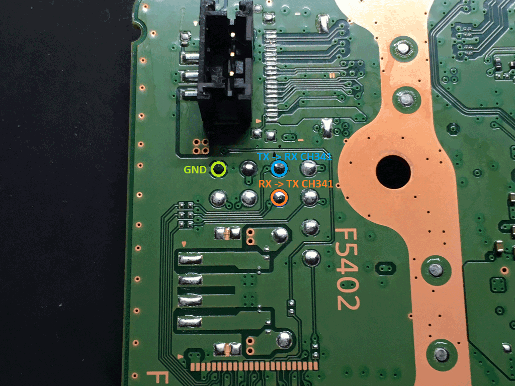
EDM-03x
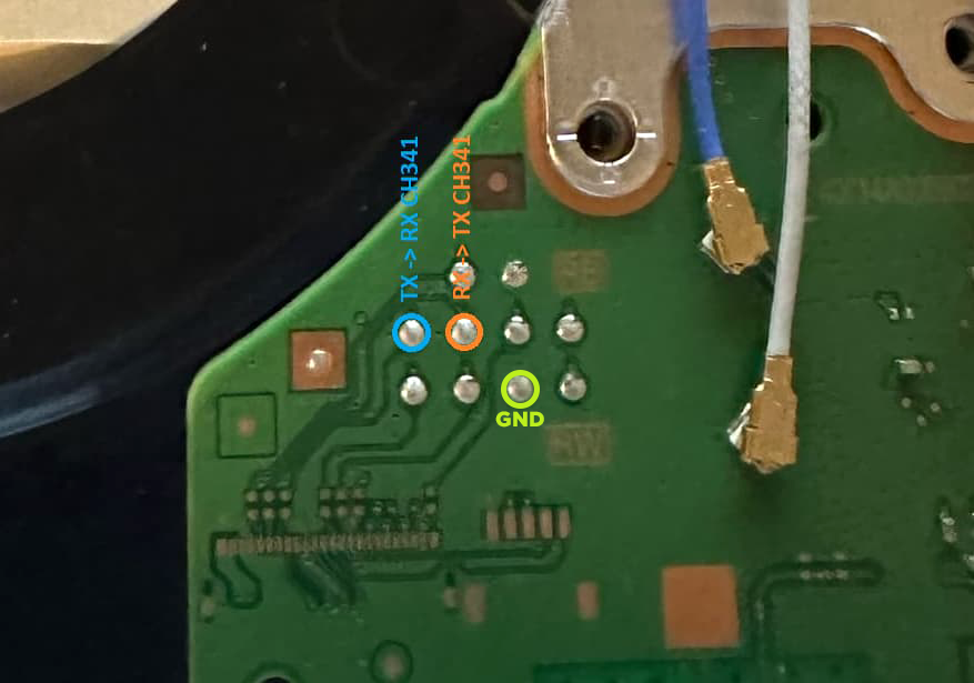
EDM-04x+
CH341A UART Module 3.3V Modification Guide
Overview
The mod is necessary to ensure compatibility with devices requiring 3.3v on the TX/RX lines, such as the PlayStation 5’s southbridge.
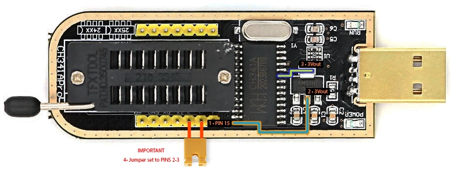
CH341A Reference Image
Steps:
-
Locate PIN 15:
- Identify PIN 15 on the CH341A IC (Reference Image labeled 1) and isolate it from the board, ensuring it doesn’t touch the original 5v pad below.
-
Soldering:
- Using two wires:
- Connect one end of the first wire to the lifted PIN 15 on the CH341A IC.
Reference Image labeled 1 - Connect the other end of the first wire to the 3Vout middle pin on the bottom of the voltage regulator.
Reference Image labeled 2 - orange and blue wire. - Connect one end of the second wire to PIN 9 on the CH341A IC.
Reference Image labeled 3 - Connect the other end of the second wire to the 3Vout top pin of the voltage regulator.
Reference Image labeled 3 - green and blue wire.
- Connect one end of the first wire to the lifted PIN 15 on the CH341A IC.
- Using two wires:
-
Verification:
- Verify that there is a 3v output on both TX and RX pins.
-
Switch CH341A Interface To TTL/UART IMPORTANT:
- Move or add a jumper to PINS labeled 2 and 3.
Reference Image labeled Important 4.
*Note: This step is important. You will not get a serial port if you do not switch or add a jumper.
- Move or add a jumper to PINS labeled 2 and 3.
-
Completion:
- Once the modifications are verified, the CH341A UART Module is ready for use with devices requiring 3.3v on the TX/RX lines.
Troubleshooting
-
Verify Hardware and Drivers:
- Ensure you have a TTL or CH341 device operating at 3.3V. Install the correct drivers and restart your computer if needed.
-
Check Device Manager:
- Navigate to Device Manager and confirm the presence of a serial port under Serial Ports. Unplug and replug your TTL/CH341 to identify the COM port.
-
Verify Connections:
- Ensure TX, RX, and GND connections are secure between your console and UART device.
-
Power Supply:
- Confirm that the console is plugged into a powered wall outlet, even if it’s powered off.
-
Read Codes:
- If you encounter “Operation Cancelled,” try swapping TX and RX wires.
-
Check Fuses and NOR:
- Inspect fuse F7003 and ensure NOR is not corrupted, as these may affect UART response.
-
Monitor Mode:
- Switch software to “Monitor” mode and reconnect the console. If no response, try swapping TX and RX again. Remember TTL-TX –> PS5-RX and TTL-RX –> PS5-TX. Tx is the mouth and Rx is the Ear. You dont talk mouth to mouth.
-
Hardware/Software Comparison:
- Test with a known working console to isolate hardware or software issues.
Questions & Answers
Q: Why does CST show more than 10 error codes?
- A: CST displays all error codes until “No Error Codes” response is received from the console, providing a clearer understanding of the issue.
Q: I Keep getting “Operation Cancelled” do you know why?
- A: If all connections are correct, a dead southbridge may be the cause. Refer to troubleshooting for detailed steps.
Recommended Hardware
- For optimal performance, use a 3.3V UART interface. We recommend USB to TTL converters such as this one. If using a CH341, ensure it has a 5V to 3.3V switch or perform the necessary modifications.
Fuse Information and Details
- F5401: No UART errors when pulled; console boots normally.
- F5402: Disk Drive; no UART errors displayed; console boots normally.
- F7502: Storage Controller; specific error codes displayed.
- F7003: No UART errors when pulled; console boots normally.
- F7501: External M.2 Storage; no UART errors displayed.
- F3502: Pending; no UART errors displayed.
- NOR: Bad/Corrupted/Missing; no UART response, with 3 quick beeps.
Additional Tips for UART Usage
- UART codes can be thrown from standby or power-on states. Read and save any codes, then clear the error log.
- After clearing, unplug the console, wait 5 seconds, then plug it back without powering on. Read error codes again; issues may be related to standby.
- Finally, power on the console and read codes. Focus on issues related to power-on.
A Project in Works by Fix MY
- Visit Fix MY for console repairs in Utah!
Want to Help or Contribute?
- We are seeking donor boards to advance this project. Contact us at [email protected] to contribute.